
IBM Model M USB-C Replacement Controller
23 Dec 2022 I was browsing Deskthority and saw this post about an aftermarket Model M controller purchased from Taobao. My SSK has been sitting around for a while and I’ve grown accustomed to the programmability of the ergodox I use every day. So this sounded like the perfect upgrade I was looking for.
It also looked to be a complete solution I could just easily swap with the stock controller. This didn’t turn out to be the case.
I was browsing Deskthority and saw this post about an aftermarket Model M controller purchased from Taobao. My SSK has been sitting around for a while and I’ve grown accustomed to the programmability of the ergodox I use every day. So this sounded like the perfect upgrade I was looking for.
It also looked to be a complete solution I could just easily swap with the stock controller. This didn’t turn out to be the case.
Finding the Taobao listing
The first issue was finding this. Reverse photo searches came up with nothing, I couldn’t find it on Taobao conversion sites by searching what I thought were bang on keywords.
However, the photos on Deskthority show the board which has the creators email address on, so I sent an email.
I got a reply in 5 days with a picture of the listing on Taobao and a note saying there was a new revision.
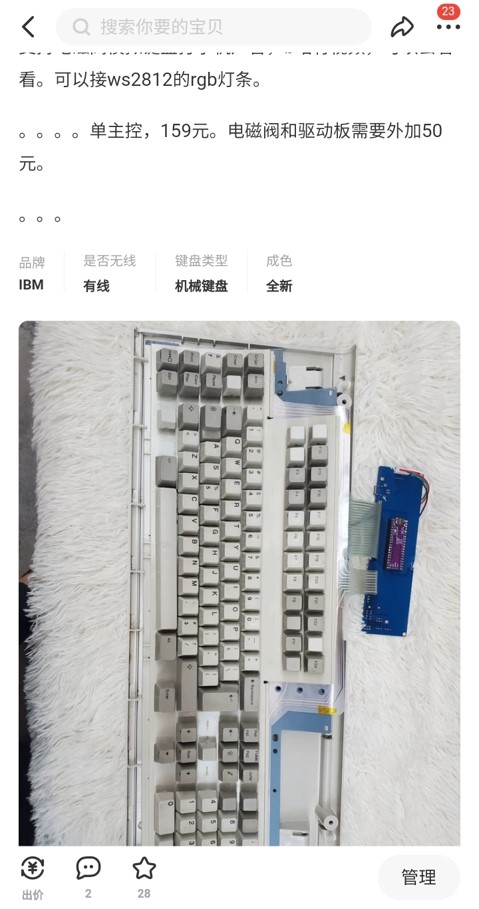 Unfortunately the creator did not send a link. I tried my hardest again to find it using the keywords I could see in the image, but no luck.
I posted that image on Deskthority and within 5 minutes someone sent me a link. So thank you so much Crizender!
The total cost came to 39.76 USD and I purchased it through superbuy.com
Here is the product link on taobao
Arrival
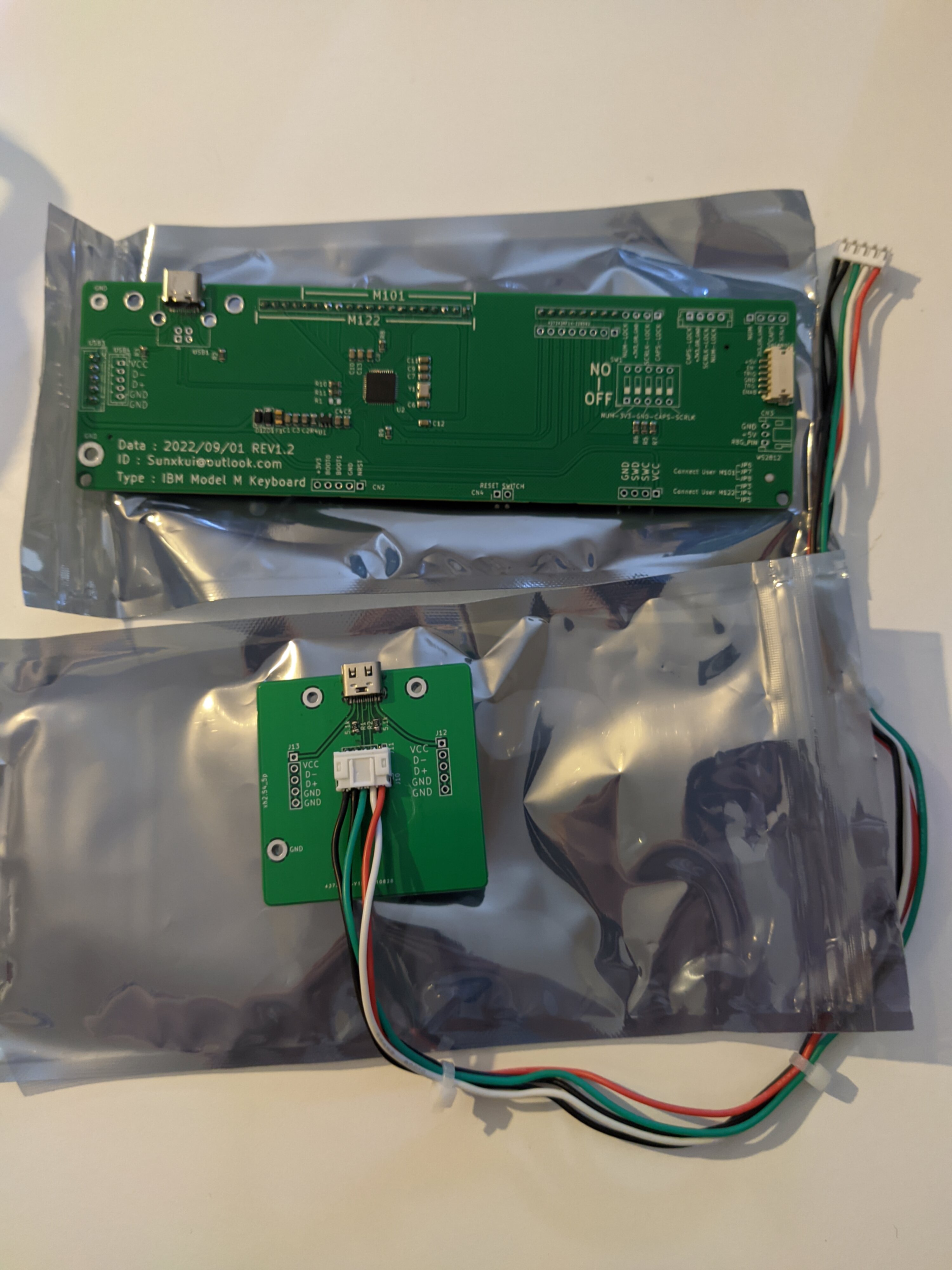 Apologies for the photo quality throughout. The Poco F3 camera is substandard
I was overjoyed when it arrived, the most exciting thing to happen since sliced bread.
Problem 1
The first problem, is that this wasn’t made for the SSK but for the larger Model M’s, so I was just assuming it would be compatible. At the very least some keys would work when it was plugged in. This did turn out to be true, it sort of worked when I plugged it in. But I’d have to write new firmware.
Unfortunately again, I couldn’t get any firmware off the creator, so I only had whatever it came with, which was no use to me.
Problem 2
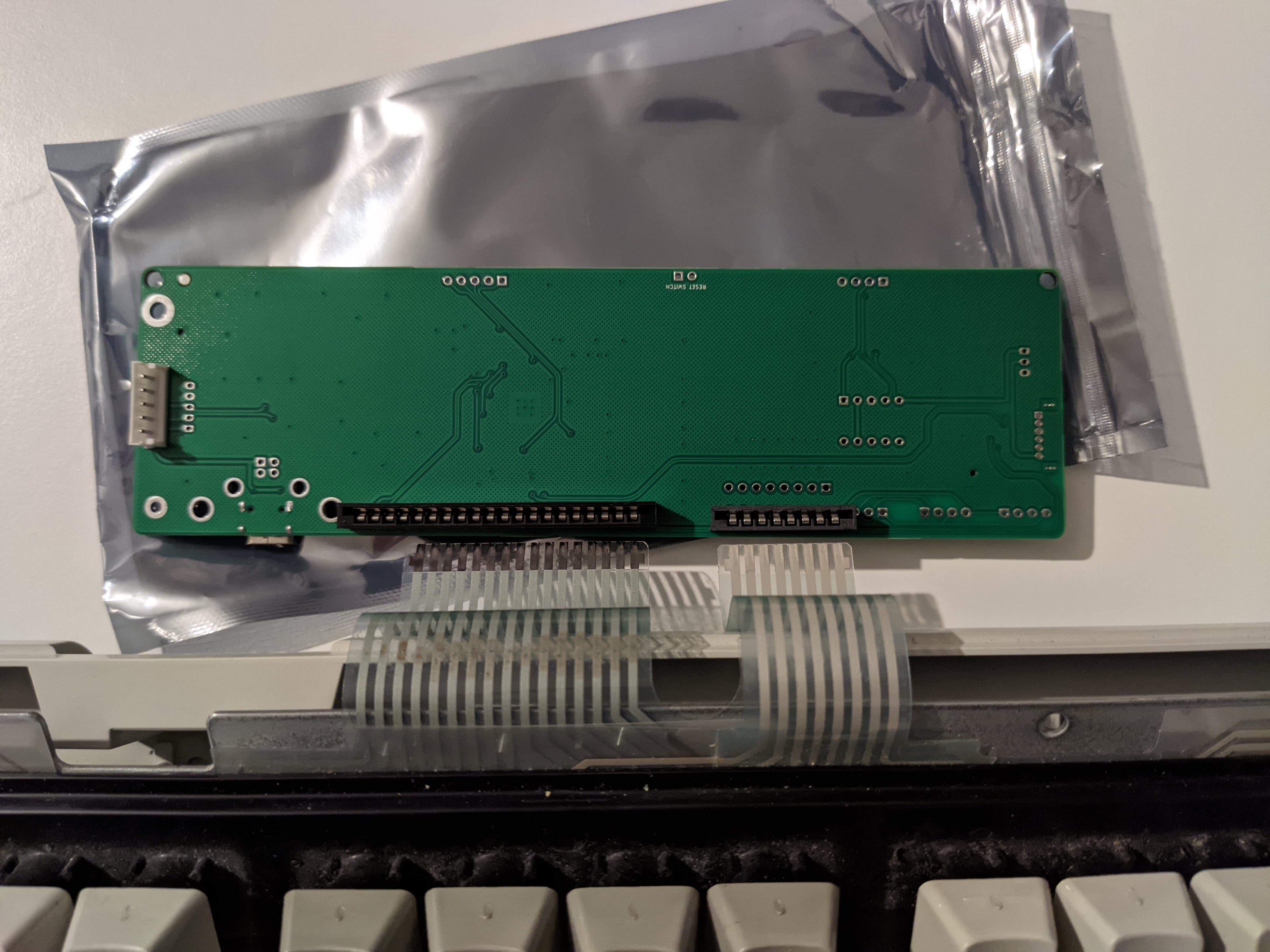 This is what it looked like when it was plugged in. It took me a while to realise that it wouldn’t fit in the case… it would have to be curled round with the ribbon cables being bent to an extreme. Hmmmmmmm
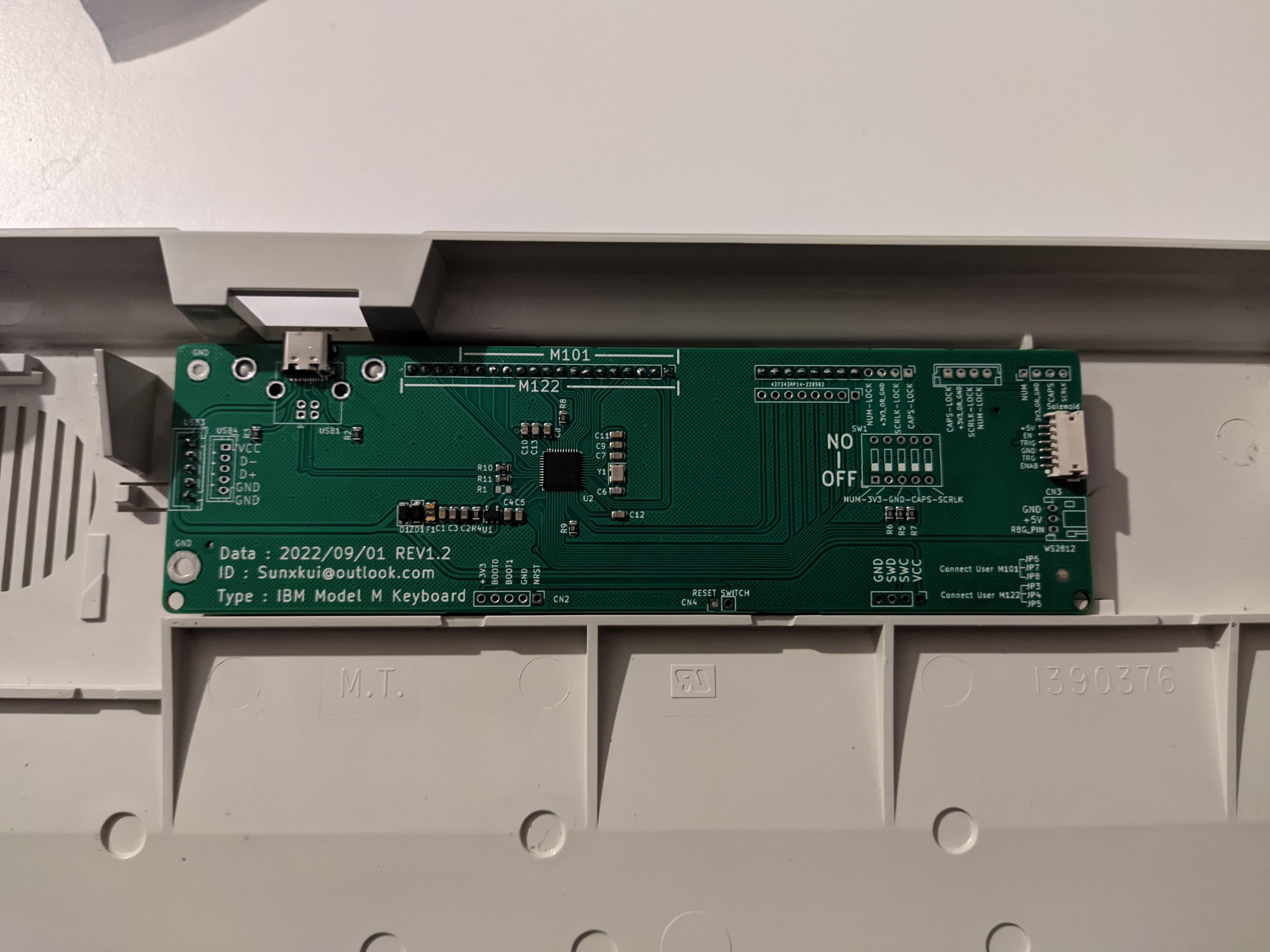
This is the controller in the case, as you can see I can’t access the sockets to plug in the cables.
I could complain (and I will) but this was how it was pictured in the Taobao listing. However, earlier revisions of this board had the ribbon sockets on the front, which made more sense to me.
I didn’t think there was any value in going any further with this if I couldn’t fit it in the case. I didn’t want it hanging out the back like in the pictures.
Not wanting to give up on my dreams, I thought I could de-solder the connectors and put them on the front! So I did!
To my surpise this went off without a hitch, I didn’t badly damage the board in the de-soldering process, and it still seemed to be working!
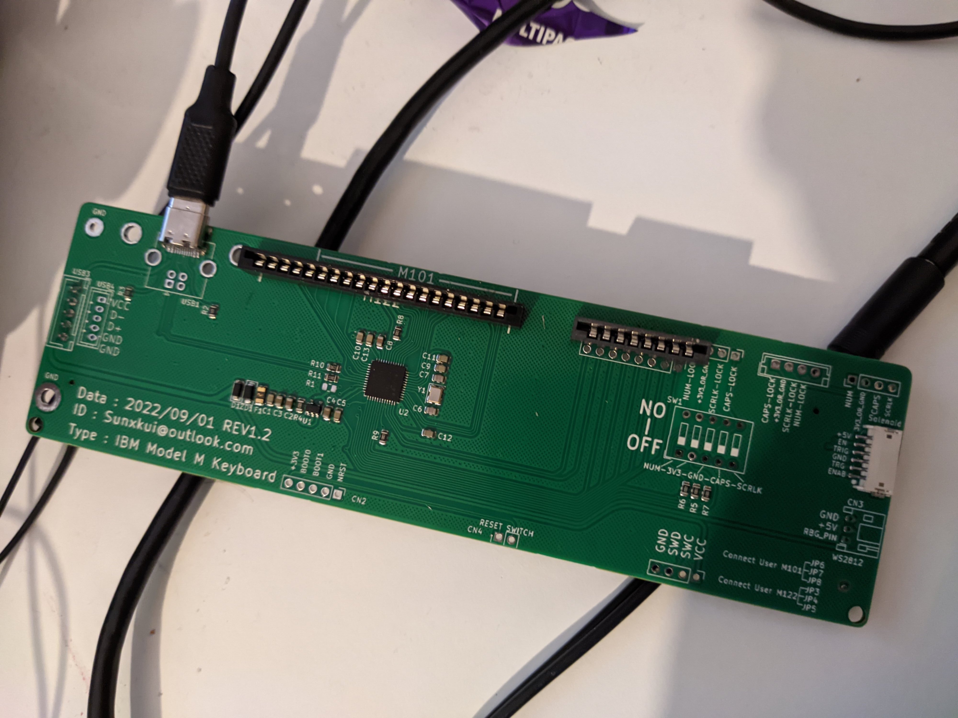
So now it would fit in the case when plugged in.
Making the firmware
I’ve done a couple of QMK conversions in the past, but they were easier than this. Since I didn’t have any source code from the creator, I was thinking I would have to start from scratch. Luckily this is not the first custom controller for the SSK (but maybe the first running QMK!).
A lot of credit here goes to PhosphorGlow who ran or still does a model m restoration service and used to sell replacement controllers.
 Link to initial creation of a custom SSK controller on a teensy
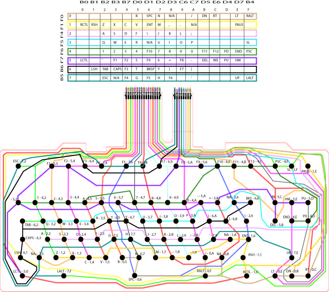
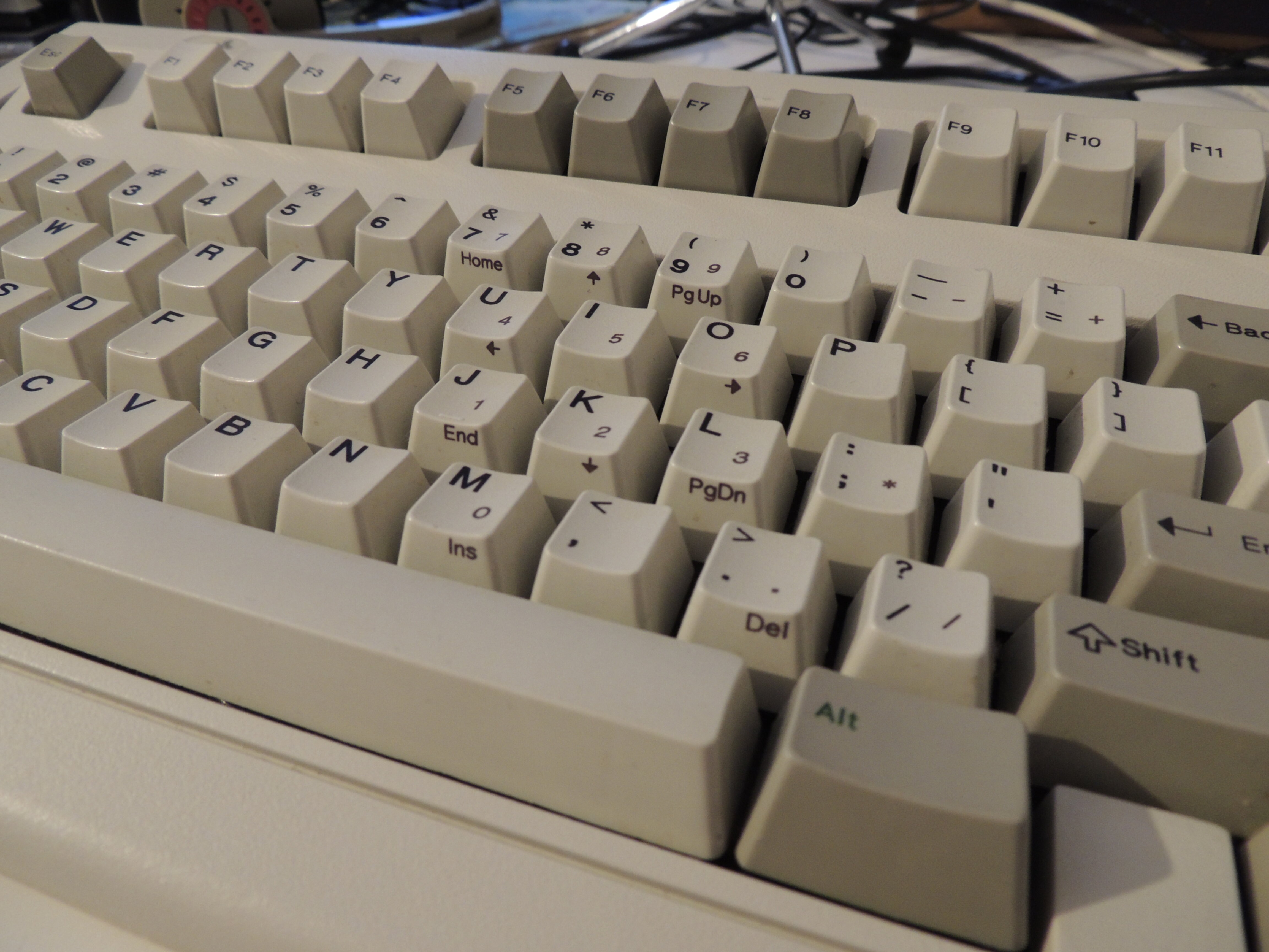
This is a picture of the SSK’s matrix and honestly all I feel when I look at this is confusion. But I am so thankful for this as it meant I didn’t have to open my SSK which is screw-modded to study the matrix.
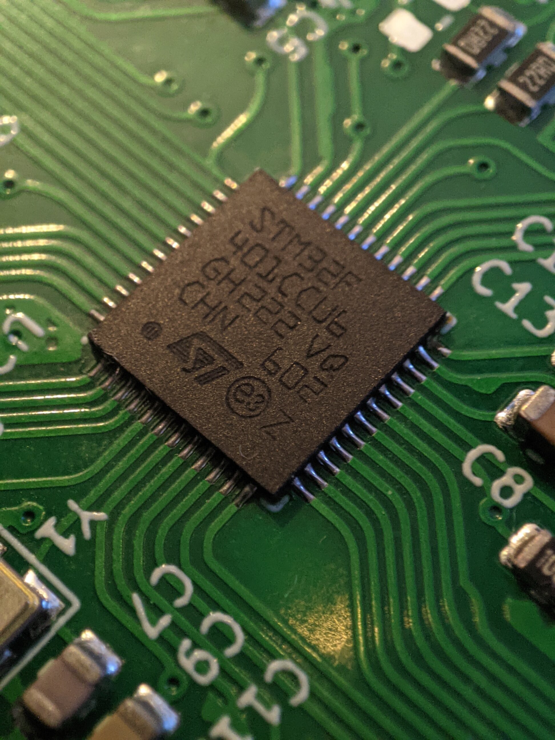
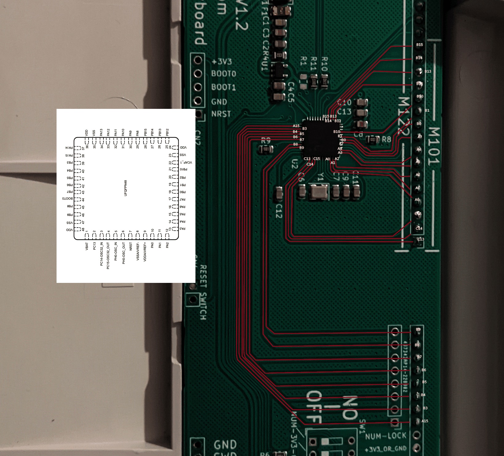
Now I had the matrix, I needed to map the pins. This controller has a STM32F401 on it which luckily is supported by QMK.
 Mapping the pins in theory is really simple, you just follow the traces and write down the pin as it’s labeled in the datasheet. What I didn’t account for is me being an idiot.
Through the process of mapping the keys I found one of my columns being attached to a VDD pin. Even with my limited knowledge I knew this to be incorrect. VDD is not an I/O pin but for power, so this could not be correct.
So I checked I had traced the board correctly, and I had. I was so confused but knew I must have been doing something wrong. This lead to my Google search of “which way up does a chip go?”
I had assumed the text acted as some sort of this way up indicator. This was wrong to assume. I found this fantastic article on different chips and how they identify pin one. The long and short of it is the indentation (Polarity marker) indicates pin 1. Now I knew this I rotated pinout diagram 90 degrees and there we go. I’d cracked it.
So I created a list of pins and what rows and columns they related to.
 It’s a tiny piece of paper
Now I knew what pins were used, I needed to map the config.h layout mappings. Luckily again, I could copy what PhosphorGlow created for their controller.
#define KEYMAP( \
    K72,      K53, K54, K64, K74, K76, K78, K69, K59, K56, K46, K4B, K4C,      K4F, K3F, K1E, \
    K52, K42, K43, K44, K45, K55, K57, K47, K48, K49, K4A, K5A, K58, K36, K66, K5C, K5E, K5D, \
    K62, K32, K33, K34, K35, K65, K67, K37, K38, K39, K3A, K6A, K68, K26,      K5B, K4E, K4D, \
    K63, K22, K23, K24, K25, K75, K77, K27, K28, K29, K2A, K7A, K1A, K16, \
    K61, K73, K12, K13, K14, K15, K05, K07, K17, K18, K19, K0A, K08, K11,           K7E, \
    K50,      K7F,                     K06,                K0F,      K10,      K0E, K0B, K0C \
) { \
    { KC_NO,    KC_NO,    KC_NO,    KC_NO,    KC_NO,    KC_##K05, KC_##K06, KC_##K07, KC_##K08, KC_NO,    KC_##K0A, KC_##K0B, KC_##K0C, KC_NO,    KC_##K0E, KC_##K0F }, \
    { KC_##K10, KC_##K11, KC_##K12, KC_##K13, KC_##K14, KC_##K15, KC_##K16, KC_##K17, KC_##K18, KC_##K19, KC_##K1A, KC_NO,    KC_NO,    KC_NO,    KC_##K1E, KC_NO }, \
    { KC_NO,    KC_NO,    KC_##K22, KC_##K23, KC_##K24, KC_##K25, KC_##K26, KC_##K27, KC_##K28, KC_##K29, KC_##K2A, KC_NO,    KC_NO,    KC_NO,    KC_NO,    KC_NO }, \
    { KC_NO,    KC_NO,    KC_##K32, KC_##K33, KC_##K34, KC_##K35, KC_##K36, KC_##K37, KC_##K38, KC_##K39, KC_##K3A, KC_NO,    KC_NO,    KC_NO,    KC_NO,    KC_##K3F }, \
    { KC_NO,    KC_NO,    KC_##K42, KC_##K43, KC_##K44, KC_##K45, KC_##K46, KC_##K47, KC_##K48, KC_##K49, KC_##K4A, KC_##K4B, KC_##K4C, KC_##K4D, KC_##K4E, KC_##K4F }, \
    { KC_##K50, KC_NO,    KC_##K52, KC_##K53, KC_##K54, KC_##K55, KC_##K56, KC_##K57, KC_##K58, KC_##K59, KC_##K5A, KC_##K5B, KC_##K5C, KC_##K5D, KC_##K5E, KC_NO },  \
    { KC_NO,    KC_##K61, KC_##K62, KC_##K63, KC_##K64, KC_##K65, KC_##K66, KC_##K67, KC_##K68, KC_##K69, KC_##K6A, KC_NO,    KC_NO,    KC_NO,    KC_NO,    KC_NO },  \
    { KC_NO,    KC_NO,    KC_##K72, KC_##K73, KC_##K74, KC_##K75, KC_##K76, KC_##K77, KC_##K78, KC_NO,    KC_##K7A, KC_NO,    KC_NO,    KC_NO,    KC_##K7E, KC_##K7F }  \
}

#endif
This is config for TMK Hasu’s firmware, which has slightly different syntax than QMK. I just needed to remove “KC_##” from the bottom section.
Skipping over the rest of configuring a QMK project that was pretty much it. Now I have a working, programmable, USB-C, replacement controller for my SSK. This thing is fantastic.
I also added vial support, so you can do on the fly changing of the keymap.
I’ve added it to my fork of vial-qmk so if you want to purchase one of these for an SSK you can have an easier time than me.
Typed on SSK
